


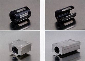
LM Bushing,Ball Bushings
Negotiable Min Order Quantity Unit
- Required Quantity
-
- Place of Origin
- Payment Terms
- Negotiable
- Production method
- Negotiable
- Shipping / Lead Time
- Negotiable / Negotiable
- Keyword
- Category
- Pipe Fittings
Apply a video call to the Supplier
![]()
Korea Lintec Shaft
 South Korea
- Verified Certificate
-
14


| Product name | LM Bushing,Ball Bushings | Certification | - |
|---|---|---|---|
| Category | Pipe Fittings | Ingredients | - |
| Keyword | - | Unit Size | - |
| Brand name | - | Unit Weigh | - |
| origin | Stock | - | |
| Supply type | - | HS code | - |
Product Information
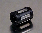
| LM BUSHING | ||
 |
 |
 |
|
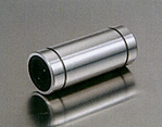
LM, LME, LMB
|
LM-AJ, LME-AJ, LMB-AJ
|
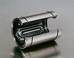
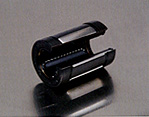
LM-OP, LME-OP, LMB-OP
|
 |
 |
 |
|
LM-L, LME-L
|
LM-A, LME-A, LMB-A
|
Compact Range
KH Series |
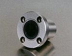
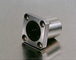
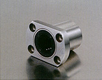
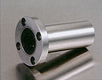
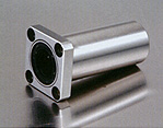
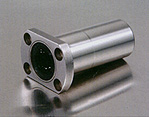
| FLENGED TYPE IM BUSHING | ||
 |
 |
 |
|
LMF, LME F, LMB F
|
LMK, LME K, LMB K
|
LMH
|
 |
 |
 |
|
LMF-L, LME F-L
|
LMK-L
LME K-L |
LMH-L
|
| SUPER LM BUSHING | ||
 |
 |
|
|
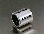
LMES, LMBS
|
LMES-OP, LMBS-OP
|
|
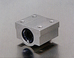
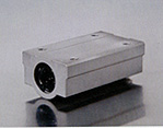
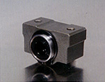
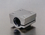
| LM BUSHING CASE UNIT | ||
 |
 |
 |
|
SC, SCE
|
SC-W, SCE-W
|
SC-V, SCE-V
|
 |
||
|
SCJ
|
||
KLS LM Bushing-Interchangeability List
Ball Bushing-Compact Type
|
KLS
|
NTN
|
STAR
|
INAA
|
SKF
|
FAG
|
|
KH..
|
KH..
|
0658-0..-00
|
KH..
|
LBBR..
|
LNA..
|
|
(LBBS..)
|
(LFA..)
|
||||
|
KH.PP
|
KH..LL
|
0658-2..-40
|
KH..PP
|
LBBR..2LS
|
LNA..2RS
|
|
(LBBS..2LS)
|
(LFA..2RS)
|
Ball Bushing-Resin Retainer
|
KLS
|
NB
|
THK
|
EASE
|
|
LM..
|
SM..G
|
LM..
|
SDM..
|
|
LM..UU
|
SM..GUU
|
LM..UU
|
SDM..UU
|
|
LM..UUAJ
|
SM..GUUAJ
|
LM..UUAJN
|
SDM..UUAJ
|
|
LM..OP
|
SM..GOP
|
LM..OP
|
SDM..OP
|
|
LM..UUOP
|
SM..GUUOP
|
LM..UUOP
|
SDM..UUOP
|
| *The above types are metric dimension series generally used in Japan and other countries. | |||
|
KLS
|
NB
|
THK
|
EASE
|
|
LMB..
|
SW..G
|
LMB..
|
SDB..
|
|
LMB..UU
|
SW..GUU
|
LMB..UU
|
SDB..UU
|
|
LMB..AJ
|
SW..GAJ
|
LMB..AJ
|
SDB..AJ
|
|
LMB..UUAJ
|
SW..GUUAJ
|
LMB..UUAJ
|
SDB..UUAJ
|
|
LMB..OP
|
SW..GOP
|
LMB..OP
|
SDB..OP
|
|
LMB..UUOP
|
SW..GUUOP
|
LMB..UUOP
|
SDB..UUOP
|
| *The above types are inch dimension series generally used in U.S | |||
|
KLS
|
NB
|
INA
|
SKF
|
THK
|
IKO
|
IKO
|
EASE
|
|
LME..
|
KB..G
|
KB..
|
LBAR/LBCR..
|
LME..
|
LBE..
|
MA M..
|
SDE..
|
|
LME..UU
|
KB..GUU
|
KB..PP
|
LBAR/LBCR..2LS
|
LME..UU
|
LBE..UU
|
MA M..WW
|
SDE..UU
|
|
LME..AJ
|
KB..GAJ
|
KBS..
|
LBAS..
|
LME..AJ
|
LBE..AJ
|
MA M..ADJ
|
SDE..AJ
|
|
LME..UUAJ
|
KB..GUUAJ
|
KBS..PP
|
LBAS..2LS
|
LME..UUAJ
|
LBE..UUAJ
|
MA M..ADJ WW
|
SDE..UUAJ
|
|
LME..OP
|
KB..GOP
|
KBO..
|
LBAT/LBCT
|
LME..OP
|
LBE..OP
|
MA M..OPN
|
SDE..OP
|
|
LME..UUOP
|
KB..GUUOP
|
KBO..PP
|
LBAT/LBCT..2LS
|
LME..UUOP
|
LBE..UUOP
|
MA M..OPN WW
|
SDE..UUOP
|
| *The above types are metric dimension series generally used in Europe. | |||||||
Load Rating
Basic Dynamic Load Rating (C)
This term is arrived at based on an evaluation of a number of identical linear systems individually run in the same conditions, if 90% of them can run with the load (with a constant value in a constant direction) for a distance of 50km without damage caused by rolling fatigue. This is the basis of the rating.
Allowable Static Moment (M)
This term defines the allowable limit value of static moment load, with reference to the amount of permanent deformation similar to that used for evaluation of basic rated load(Co).
Static Safety Factor (fs)
This factor is used based on the application condition as shown in Table 1.
Basic Static Load Rating (Co)
This term defines a static load such that, at the contacting position where the maximum stress is exercised, the sum of the permanent deformation of the rolling elements and that of the rolling plane is 0.0001 time of the diameter of the rolling elements.
Table1. Static Safety Factors
|
Condition of use
|
Low limit of fs
|
|
When the shaft has less deflection and shock
|
1 to 2
|
|
When elastic deformation should be considered with respect to pinch load
|
2 to 4
|
|
When the equipment is subject to vibration and impacts
|
3 to 5
|
Rating Life
Rating Life of the Linear System
As long as the linear system reciprocastes while being loaded, continuous stress acts on the linear system to cause flaking on the rolling bodies and planes because of material fatigue. The travelling distance of linear system. The life of the system varies even for the systems of the same dimensions, structure, material, heat treatment and processing method, when used in the same conditions. This variation is brought about from the essential variations in the material fatigue itself. The rating life defined bellow is used as an index for the life expectancy of the linear system.
Rating Life (L)
Rating life is the total travelling distance that 90% of a group of systems of the same size can reach without causing andy flaking when they operate under the same conditions.
The rating life can be obtained from the following equation with the basic dynamic load rating and the load on the linear system:
![]()
L: Rating life(km), C: Basic dynamic load rating(N). P: Load(N)
Consideration and influence of vibration impact loads and distribution of load should be taken into account when designing a linear motion system, It is difficult to calculate the actual load. The rating life is also affected by the operating temperature. In these conditions, the expression(1) is arranged as follows:
![]()
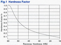
L: Rating life(Km), fh: Hardness factor(See Fig.1)
C: Basic hynamic load rating(N)
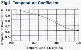
fr: Temperature coefficient(See Fig.2), P: Load (N)
fc: Contact coefficient (see Table 2)
fw : Load Coefficient (See Table 3)
The rating life in hours can be calculated by obtaining the travelling distance per unit time. The rating life in hours can be obtained from the following expression when the stroke length and the number of strokes are constant:
![]()
Lh: Rating life in hours(hr)
ls: Stroke Length(m)
L: Rating life(km)
n: No of strokes per minute(cpm)
| Hardness Factor(fH) The shaft must be sufficiently hardened when a linear bushing is used. If not properly hardened, permissible load is lowered and the life of the bushing will be shortened. |
 |
||||||||||||
| Temperature Coefficient(fr) If the temperature of the linear system exceeds 100°C, hardness of the linear system and the shaft lowers to decrease the permissible load compared to that of the linear system used at room temperature. As a result, the abnormal temperature rise shortens the rating life. |
 |
||||||||||||
| Contact Coefficient(fc) Generally two or more linear bushings are used on one shaft. Thus, the load on each linear system differs depending on each processing accuracy. Because the linear bushings are not loaded equally, the number of linear bushings per shaft changes the permissible load off the system. |
Table 2 Contact Coefficient
|
||||||||||||
| Load Coefficient(fw) When calculating the load on the linear system, it is necessary to accurately obtain object weight, inertial force based on motion speed, moment load, and each transition as time passed. However, it is difficult to calculate those values accurately because reciprocating motion involves the repetition of start and stop as well as vibration and impact. A more practical approach is to obtain the load coefficient by taking the actual operating conditions into account. |
Table 3 Load Coefficient
|
Frictional Resistance
The static frictional resistance of the KLS LM Sytem is so low as to be only slightly different for the kinetic frictional resistance, enabling smooth linear movement from low to high speeds. Ingeneral, the frictional resistance is expressed by the following equation.
F= μ x W+f
F: Frictional resistance, μ: Coefficient of friction
W: Load weight, f: Sealing resistance
The frictional resistance of each KLS LM system depends on the model, load weight, speed, and lubricant. The sealing resistance depends on the lip interference and lubricant, regardless of the load weight. The sealing resistance of one linear system is about 200 to 500gf. The coefficient of friction depends on the load weight, moment load, and preload. Table 6 shows the coefficient of kinetic friction of each type of linear system which has been installed and lubricated properly and applied with normal load(P/C=0.2)
Table 5 Coefficient of Linear System Friction(μ)
|
Linear System Type
|
Models
|
Coefficient of Firction(μ)
|
|
Linear Bushing
|
LM LME LMB
|
0.002 to 0.003
|
Ambient Working Temperature
|
The ambient working temperature range for each KLS LM system depends on the model. Consult KLS on use outside the recommended temperature range. Temperature conversion equation |
Table 6 Ambient Working Temperature
|
Lubrication and Dust Prevention
using KLS LM Systems without lubrication increases the abrasion of the rolling elements, shortening the life span. The KLS LM Systems therefore require appropriate lubrication. For lubrication KLS recommends turbine oil conforming to ISO Standards G32 to G68 or lithium base soap grease No.2. Some KLS LM systems are sealed to block dust out and seal lubricant in. If used in a harsh or corrosive environment, however, apply a protective cover to the part involving linear motion.
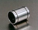
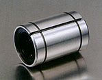
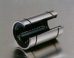
Structure and Features
- The KLS LM bushing consists of an outer cylinder, ball retainer, balls and two end rings. The ball retainer which holds the balls in the recirculating trucks in held inside the outer cylinder by end rings.
- Those parts are assembled to optimize their required functions.
- The outer cylinder is maintained sufficient hardness by heat treatment, therefore if ensures the bushings projected travel life and satisfactory durability.
- The ball retainer is made from steel or synthetics resin. The steel retainer has high rigidity, obtained by heat treat meant. The synthetics resin retainer can reduce running noise. The user can select the optimum type for meeting the user's service conditions.

1. High precision and Rigidity
The KLS LM bushing is produced from a solid steel outer cylinder and incorporates an industrial strength resin retainer.
2. Ease of Assembly
The standard type of KLS LM bushing can be loaded from any direction. Precision control is possible using only the shaft supporter, and the mounting surface can be machined easily.
3. Ease of Replacement
KLS LM bushigs of each type are completely interchangeable because of their standardized dimensions and strict precision control. Replacement because of wear or damage is therefore easy and accurate.
4. Variety of Types
KLS offers a full line of linear bushing: the standard, integral single-retainer closed type, the clearance adjustable type and the open types. The user can choose from among these according to the application requirements to be met.
Types and LM Bushing Number
Example

Tolerance
Note that precision of inscribed circle diameters and outside diameters for the clearance adjustable type(...-AJ) and the open type(...-OP) indicates the value obtained before the corresponding type is subjected to cutting process.
Load Rating and Life Expectancy
The life(L) of a linear bushing can be obtained from the following equation with the basic dynamic load rating and the load applied to the bush:
![]()
L: Rated life(km), fH: Hardness factor
C: Basic dynamic load rating (N), fT: Temperature coefficient
P: Working load(N), fC: contact coefficient
fw: Load coefficient
The lifespan(Ln) of a linear bushing in hours can be obtained by calculating the travelling distance per unit tine. The lifespan can be obtained from the following equation if the stroke length and the number of strokes are constant:
![]()
Lh: Lifespan(hr), s: Stroke length(m)
L: Rated life(km), n1:Number of strokes per minute(cpm)
Relation between ball
Circuits and load rating
The KLS LM bushing includes ball circuits that are spaced equally and circumferentially. The load rating varies according to the loaded position on the circumference.
Teh value the dimension table indicates the load rating when the load is placed on the opt of one ball circuit. If the KLS LM bushing is used with two ball circuits loaded uniformly, the load rating will be greater. The following table shows the values by the number of ball circuits in such cases:

Clearance and Fit
When a standard-type KLS LM bushing is used with a shaft, inadequate clearance, adjustment may cause early bush failure and/or poor, rough travelling. The clearance adjustable linear bush and open linear bush can be clearance adjusted when assembled in the housing which can control the outside cylinder diameter. However, too much clearance adjustment increases the deformation of the outside cylinder, to affect its precision and life. Therefore, the appropriate clearance between the bush and shaft, and clearance between the bush and housing are reqquired according to the application. Table 2 shows recommended fit of the bush:
Table 2
| Model | Division | Shaft | Housing | ||
| Normal fit | Transitional | Loose fit | Tight fit | ||
| LM LMB |
High class | g6 | h6 | H7 | J7 |
| LME | High class | h6 | j6 | h7 | j7 |
| Note: The clearance may be zero or negative. Please attention the movement | |||||
Shaft and Housing
To optimize performance of the KLS LM bushing high precision of the shaft and housing is required.
1. Shaft
The rolling balls in the KLS LM bushing are in point contact with the shaft surface. Therefore, the shaft dimensions, tolerance, surface finish, and hardness greatly affect the travelling performance of the bush. The shaft should be manufactured with due attention to the following points:
1) Since the surface finish critically affects smooth rolling of balls, grind the shaft at 1.5 S or better.
2) The best hardness of the shaft is HRC 60 to 64. Hardness less than HRC 60 decreases the life considerably, and hence reduces the permissible load. On the other hand, hardness over HRC 64 accelerates ball wear.
3) The shaft diameter for the clearance adjustable linear bush and open linear bush should as much as possible be of the lower value of the inscribed circle diameter in the specification table. Do not set the shaft diameter to the upper value.
4)Zero clearance or negative clearance increases the frictional resistance slightly. If the negtive clearance is too tight, the deformation of the outside cylinder will become larger, to shorten the bush life.
2. Housing
There is a wide range of housings differing in design, machining, and mounting. For the fitness and shapes of housings, see Table 2 and the following section on mounting.
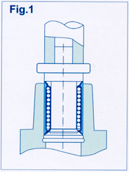
| Mounting When inserting the linear bush into the housing, do not hit the linear bush on the side ring holding the retainer but apply the cylinder circumference with a proper jig and push the linear bush into the housing by hand or lightly knock it in. (See Fig.1) |
 |
Examples of Mounting
The Popular way to mount a linear bush is to operate it with an appropriate interference. It is recommended, however, to make a loose fit in principle because otherwise precision is apt to be minimized. The following examples(Figs.2 to 6) show assembling of the inserted bush in terms of designing and mmounting, for reference.

B2B Trade
| Price (FOB) | Negotiable | transportation | - |
|---|---|---|---|
| MOQ | Negotiable | Leadtime | Negotiable |
| Payment Options | Negotiable | Shipping time | Negotiable |
![]()
- President
- Woo-ho Lee
- Address
- #1208-Ga Dong(ChungAng Circulation Complex,Guro-Dong)15,Gyeongin-Ro,53-Gil, Guro-gu, Seoul, Korea
- Product Category
- High Precision Bearings
- Year Established
- 2002
- No. of Total Employees
- 1-50
- Company introduction
-
Greetings to customers all around the world!
Our company have been producing all sorts of shafts and exporting to the international market. Our brand "KLS" Shaft (Korea Lintec & Shaft) has been acknowledged for great quality control, competitive pricing, and punctual and fast delivery. Exports have been increasing continuously due to our excellent reputation of great deals and quality by our customers.
Especially, we have developed HPJ Brand's LM Bushings overseas (China), of which trademark HPJ has registered in Japan, which is used with our Shaft and we are exporting them in parallel, and has established ourselves as a maker of LM System. Any Buyers who has imported our Shaft and LM Bushings takes advantage of our
1) Competitive price
2) Top quality products
3) Fast delivery
and continues to do buy our "KLS" Brand Shafts and HPJ Brand LM Bushings. The long term relationship we maintain with these buyers are our greatest strengths.
And,also we are producing many other concerned Items such,
1) "Support Unit",
2)"Micro Coupling"
3)"Lock Nut" for Ball Screw,
4)"TM(Lead) Screw,
5)"Cross Roller Guide","Sector Elignment Stage" is No.2 in the world makers/factories
6)"Miniature Liner Guide",
7)"RodEnd & Camfollower", "Track Roller",
8)"Thrust Roller Bearings",etc.,
are all for Factory Automation Systems,and also for Robot Systems.
Therefore, in 2015, we will put our best effort into increasing our exports, and we promise you that we will be the number one Brand of above all Products in the near future.
Chief Representative: Woo Ho Lee
- Main Markets
-
 Germany
- Factory Information
-
KLS,
Korealintec & Shaft
- Main Product


Hinge_2.JPG "Clip_on_Detachable_attahable_Hinge_1")

