


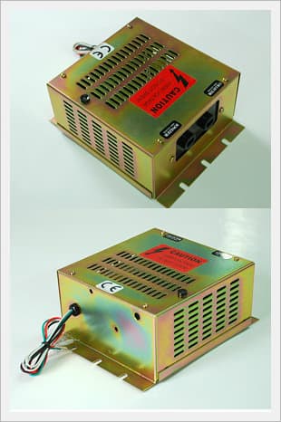
Power Supply Generator (SJ-1260AN)
Negotiable Min Order Quantity Unit
- Required Quantity
-
- Place of Origin
- Payment Terms
- Negotiable
- Production method
- Negotiable
- Shipping / Lead Time
- Negotiable / Negotiable
- Keyword
- Category
- AC/DC Adapters
Apply a video call to the Supplier
![]()
Sejin Electronics Co., Ltd.
 South Korea
- Verified Certificate
-
16


| Product name | Power Supply Generator (SJ-1260AN) | Certification | - |
|---|---|---|---|
| Category | AC/DC Adapters | Ingredients | - |
| Keyword | - | Unit Size | - |
| Brand name | - | Unit Weigh | - |
| origin | Stock | - | |
| Supply type | - | HS code | - |
Product Information
Introduction of Power Supply (Power Pack)
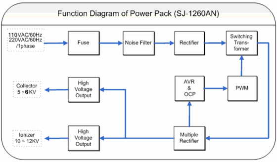
The electric precipitator consists of an Ionizing part, a Collecting cell part . This method is called as a double stage electric charge method. An ionizing part grants a High Voltage (DC 10KV~12KV) and makes an electric field, which ionizes pollutants.
Also a collecting part is formed to collect pollutants by providing a cell High Voltage (DC 5~6KV) to the collecting part. This can eliminate 0.01 µm particles dust and can be considered as the best way with more than 97% of efficiency.
Specification
- Model : SJ-1260AN
- Sources of electricity : AC 230V 10 % , 1Ø 50Hz-60Hz or AC 110V 10 % , 1Ø 50Hz-60Hz.
(It is not free voltage model but customer option.) - Output :
.IONIZER : 10KV~12KV
.COLLECTOR : 5KV~6KV - Power : 80VA
- Safety device : embedded protection circuit of surge and Overload
- Protection time : 0.1sec
- Alarm function : the outside terminal LAMP or BUZZER (selectable)
- Indication : under a normal operation or a normal load, green LED lighted whereas under an Overload (or surge), a red LED is constantly blinked.
- Dimension : H80x W145 x D155 (mm)
- Accessory : Wire (GND, IONIZER, COLLECTOR)
Function Diagram
Installation
- by the power pack wiring drawing.
- Confirm the connection between a Power Pack and an Earth.
(see the figures in the Page 3)
i. erminal :
.AC 110V 50Hz-60Hz or
.AC 220V 50Hz-60Hz (black, red Lead)
ii. GND Terminal :
.Ground terminal
.GOUND (green Lead)
iii. Condition Terminal :
.White x 2 lead state
.Condition contact ( connection ) - Confirm the connection between a terminal and electric line
- Confirm the connection of high voltage terminal in Power Pack
- DC 5KV~ 6KV ---- Terminal in Collector (Cell) side
- DC 10KV~12KV ---- Terminal in Ionizer side
- confirm exactly a connection part of high voltage terminal
- A good contacting connector must be used at connecting part and for the connection of high voltage line and an electric line a high pressure contraction tube must be used to endure enough durability and internal pressure.
Operation
- In the above 2). (Page.6), first check the clause i), ii), iii), and then turn on the power pack external power switch-NFB or SW.
- After turning it on, check whether the LED P.L in a front lower part of a POWER PACK can be lighted in green.
- If it is lighted in green, POWER PACK is in normal operation.
- Output: DC 5 ~ 6 KV (adjustable), DC 10~12 KV (adjustable).
- Simultaneous adjustable (blue VR-2 on the PCB). - Input and terminal: red& black / AC 220V or AC 110V input
: Green /Earth (ground)
: White, white / condition contact
. At present, it's in B contact. At abnormal, it maintains a contact state (when it's bickering)
. Condition contact is convertible by changing an internal connector pin to A contact.
- Remark : Green LED should be a ground connection in use. (A poor connection is the cause of a trouble ) - Indicating LED: two colored LED is on the upper side of a case. In normal, green LED is constantly lighted. In abnormal, red and green LED is alternatively lighted.
:In an instant over current and short circuit, a relay and a LED are bickering in two minutes interval.
:In constant over current and constant shirt circuit, LED is in constant bickering, and Relay is designed to prevent a Relay contact loss by maintenance of constant A contact state. - PCB coating: this enhances the durability of semiconductor element and prevents a damage of parts, so clears the cause of break.
Maintenance
- Confirm whether a terminal connection of input AC voltage or not.
- After checking Clause1), confirm the voltage of output terminal
(in measuring, use a high voltage measurement TEST PROBE) - In measuring a high voltage, firstly measures it under no-load state, then if it's normal, measure it under load state.
(At this time, connect a terminal of IONIZER and COLLECTOR) - If in normal state, green LED is constantly lighted.
- If a load is abnormal, that is to say, if it is in over-load or surge, LED is changed to red bicker. At this time, this indicates us abnormality at the side of COLLECTOR and IONIZER. Red bicker is also happened in connecting a larger quantity of cell than a Pack's capacity.
* Reference
- When this state keeps on, it means a short circuit by a wrong insulation and a foreign substance at the load side of IONIZER or the side of COLLECTOR. - The normal insulation resistance of a load side is the followings.
: IONIZER: over 100 MΩ (DC 10KV insulation resistance measuring instrument)
: COLLECTOR: over 50MΩ (DC 5KV insulation resistance measuring instrument)
* Reference
- Red LED may be turned on by a over-current circuit caused by the over-load in normal operation, collection of foreign substances, the over-load by a short circuit or a bend of Collector's plate and IONIZER wire or saw plate. But it will soon operate because POWER PACK is normal at that time. Sometimes a FUSE of PCB may break by the over shocking current of an over-load, or a low voltage. At this time, change the FUSE of a rated current.
* Reference
- FUSE 2.5A (it's changeable to the capacity of a POWER)
B2B Trade
| Price (FOB) | Negotiable | transportation | - |
|---|---|---|---|
| MOQ | Negotiable | Leadtime | Negotiable |
| Payment Options | Negotiable | Shipping time | Negotiable |
![]()
- President
- JUNG, DONG-HYOP
- Address
- 489-6, KALHYON2-DONG, EUNPYONG-KU,SEOUL
- Product Category
- Electrical Equipment
- Company introduction
-
We, Sejin Electronics Co., Ltd. have developed and produced the H.V. Power Supply, Ionizer, E.P. and Power Pack since our establishment in 1991. We currently manufacture the direct current high voltage generator. In 2003, we were ISO 9001/ KSA 2001 certified, which has equipped us to renovate the level of our quality. Also, we assure our customers satisfaction, based on our ample experience, state-of-the-art technology and our philosophy in customer-oriented service, MBO and creatier spirit. Executives and Staffs of Sejin Electronics Co., Ltd.
- Main Product


