


EMoS
Negotiable Min Order Quantity Unit
- Required Quantity
-
- Place of Origin
- Payment Terms
- Negotiable
- Production method
- Negotiable
- Shipping / Lead Time
- Negotiable / Negotiable
- Keyword
- Category
- Sensors
Apply a video call to the Supplier
EZ Infomation Technology Co., Ltd.
- Country / Year Established
-
 South Korea
/
South Korea
/
- Business type
- Others
- Verified Certificate
-
13

| Product name | EMoS | Certification | - |
|---|---|---|---|
| Category | Sensors | Ingredients | - |
| Keyword | - | Unit Size | - |
| Brand name | - | Unit Weigh | - |
| origin | Stock | - | |
| Supply type | - | HS code | - |
Product Information
1. Preface(summary?)
EMoS-SI01 is a device that transmits indoor environment data of the primary-industry swine farming. It is designed to minimize power consumption by employing Texas Instrument MSP430, which consumes 10% less power than that of the pre-existing processor.
EMoS-SI01 installed in swine facilities is structured to transmit each sensor data of temperature, humidity, illumination, and carbon dioxide per minute to monitoring computer.
Since it is very easy to amplify the implementation of detection sensor, it is possible to eliminate unnecessary overlapping cost and raise the work efficiency depending on indoor environment of the Installation area as well as users' need.
2. Details for the Products
|
Power
|
DC 9V, 300mA Adaptor
|
|
6F22 9V Battery
|
|
|
Current consumption
|
Less then 1mA
|
|
A/D connection extension
|
6 Port
|
|
RF Output power
|
1mW max.
|
|
RF Data rate
|
250kbps Max.
|
|
Antenna parameter
|
Average Gain-1dBi
|
|
Beamwidth 135°C
|
|
|
SHT71
|
Range -40~128C
|
|
Range 0~100%RH
|
|
|
S1087-01
|
Spectral response range 320~1100nm
|
|
TGS4161
|
Typical detection range 350~10,000ppm
|
|
Dimension(W x L x H)
|
100 x 160 x 55mm
|
|
Warranty
|
1Year
|
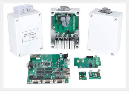
3. Structure
Figures 1, 2, and 3 shows the inner board. The board consists of RF/MCU board and MCU-sensor interface board, and RF/MCU board is attached to the upper part of the MCU-sensor interface board. RF/MCU board and MCU-sensor interface board can be detached.


Figure 4 shows the process of assembling the board and its case.
Then RF/MCU board is to be attached to the MCU-sensor interface board. At last, they are to be place in the case. The sensor is designed to be connected to the MCU-sensor interface board through the outside cable entrance marked in figure 4.

Figure 5. Structure of data transmission system network of indoor-environment breeding facility
The network structure represented in figure 5 utilizes EMoS-SI01.
Each of the provided EMoS-SI01 consists of two sensor nodes:ãÂÂone with a single "0"; the other with several sensor nodes.
The node whose node ID is "0" is to be connected to a monitoring computer. The other node is to be installed in order to detect and transmit indoor environment data. Then, finally, there is a network structure that could send and receive data wirelessly on turning on the power.
The product is designed for the users to be able to readily have a network structure just by connecting the battery and turning on the switch.

Figure 6 depicts the arrangement plan of the parts; it is to explain the connector and switch that are built in the MCU-sensor interface board.
In figure 6 SW1 is a reset switch for RF/MCU board, and SW2 is a power switch.
In figure 6 the connectors directly related to the users are J1, J2, J3, J4, and P5.
J2 and J3 are connect terminals that connect to the sensors necessary for MCU board from outside. J4 is a terminal that connects to the battery.
J1 is an augmentation connector that connects to an additional module board, and P5 is a DC jack that connects to DC adaptor.
Description of the switches and connectors
|
Parts
|
Detail | |
|
SW1
|
Reset Switch | |
|
SW2
|
Power Switch | |
|
P5
|
#006699 | |
|
J4
|
|
Battery conncetion terminal Connect the battery so that the "+" terminal of the cell is to be linked to the spot "+". |
|
J2
|
 |
Outside(exterior) sensor connection connector EXT_9V: a terminal that discharges 9V GND: basis terminal of source voltage and signal voltage ADC0: This terminal is connected to MCU ADC0 pin. (input/output pin) ADC1: This terminal is connected to MCU ADC1 pin. (input/output pin) ADC2: This terminal is connected to MCU ADC2 pin. (input/output pin) |
|
J3
|
 |
outside sensor connection connector EXT_5V: terminal that discharges 5V voltage GND: basis terminal of source voltage and signal voltage ADC3: This terminal is connected to MCU ADC3 pin. ADC4: This terminal is connected to MCU ADC4 pin. ADC5: This terminal is connected to MCU ADC5 pin. |
|
J1
|
|
sensor board connection connector 1: 5V (power pin) 2: terminal connected to MCU PORT1.6(output) - temperature/humidity sensor serial clock signal 3: a terminal connected to MCU PORT1.7(output) - 3.3 power supply terminal for temperature/humidity sensor 4: a terminal connected to MCU PORT1.5(input) - temperature/humidity sensor data input 5: CO2_HEAT(output) - carbon dioxide sensor Heating voltage 6: a terminal connected to MCU ADC4 pin (input) - carbon dioxide sensor input 7: NH3_HEAT(output) - ammonia sensor Heating voltage 8: TGS_NH_OUT(input) - ammonia sensor input 9: a terminal connected to MCU ADC0 pin (input) - PAR sensor input (illumination sensor) 10: a terminal connected to MCU ADC5 pin (input) - TSR sensor input (illumination sensor) 11: No Connection 12: GND 13: No Connection 14: GND |
4. Manufacturing
- Attach RF/MCU board to MCU-sensor interface board.
- Connect the battery to J4 connector; make sure the "+" terminal of the battery is attached to the "+" spot of the board.
- When the temperature, humidity, and illumination sensors are connected to the battery, the board assembly is to be placed on the case. Make sure the board is firmly fixed using the provided bolts.
- Connect the provided antenna to the antenna connection connector of RF/MCU board. Turn on the power switch, and assemble the case cover using the bolts.
- Repeat the same procedure 1-4 for each sensor node.
- Then, connect the node whose ID is "0" among the properly assembled and powered up ones, to the monitoring computer.
Sensor Board

Details of the sensor board
|
Parts
|
Details | |
|
U1
|
 |
CO2 Sensor 1: Heater (+) 2: Sensor electrode (+) 3: Sensor electrode (-) 4: Heater (-) |
|
U3
|
 |
NH3 Sensor - Optional 1: Heater 2: Sensor (-) 3: Sensor (+) 4: Heater |
|
U4
|
|
Atmosphere temperature/humidity (SHT71) connection terminal 1: SCK 2: VDD 3: GND 4: DATA |
|
D1
|
|
Illumination sensor connection connector 1: S1087-01 PAR illumination sensor Anode 2: S1087-01 PAR illumination sensor Cathode |
|
D2
|
|
Illumination (TSR) sensor connection connector 1: S1087 TSR illumination sensor Anode 2: S1087 TSR illumination sensor Cathode |
|
J1
|
|
sensor board connection connector 1: 5V(power pin) 2: A terminal connected to MCU PORT1.6 (input) - temperature/humidity sensor serial clock signal 3: A terminal connected to MCU PORT1.7 (input) - temperature/humidity sensor 3.3V power supply terminal 4: A terminal connected to MCU PORT1.5 (output) - temperature/humidity sensor data output 5: CO2_HEAT(input) - CO2 sensor Heating voltage 6: A Terminal connected to MCU ADC4 pin (output) - CO2 (phosphate) sensor output 7: NH3_HEAT(input) - ammonia sensor Heating voltage 8: TGS_NH_OUT(output) - ammonia sensor output 9: A terminal connected to MCU ADC0 pin (output) - PAR sensor output (illumination sensor) 10: A terminal connected to MCU ADC5 pin(output) - TSR sensor output (illumination sensor) 11: No Connection 12: GND 13: No Connection 14: GND |
4. Method of switching sensor(On/Off)
While there are a variety of sensors in the market, gas detection sensor shows such high power consumption that one can find difficulty when applying it to a low power system.
This product, however, has an independent switching circuit so that it is possible to switch the VCC supply voltage of high power consuming gas sensor within the program.
Details of sensor power supply connection
|
Operation terminal
|
Connection terminal
(MCU) |
|
|
Ammonia sensor preheating power supply
|
NH_HEAT
|
Port 2.5
|
|
CO2 sensor preheating power supply
|
CO2_HEAT
|
Port 3.0
|
|
Ammonia sensor amplifier circuit power supply
|
TGS_NH_OUT
|
Port 4.0
|
|
Outside sensor 5V power supply
|
EXT_5V
|
Port 5.1
|
|
Outside sensor 9V poer supply
|
EXT_9V
|
Port 5.2
|
5. After Sales Service Policy
We guarantee the quality of our products to have passed Quality Control with the strict tests.
1. We will only be held responsible for defected products which have normal statuses under the usual handling during the ONE year warranty period. However, any product which has been handled under the 3rd clause is to be paid for the service fee even during the warranty period.
2. Paid Service
1) An error/failure due to the customers' negligence
2) Defects by unqualified handling of the service person who is not from our sales representatives or technicians.
3) Failure or defects due to wrong installations or impact of mishandling (for example dropping during transportation)
4) Due to an electric voltage or caused by defective device which is attached with out products.
5) Other failure due to a natural disaster such as fire or flood.
6) If you request after sales service without any failure of our products, you maybe required to pay for the service charges.
3. Customers still can get paid services after the warranty period with the maintenance contract or upon requests.
* Please contact your retailer first if you need any assistance, then you can get after sales service directly from our headquarters in case the problems can not be handled by the retailer.
B2B Trade
| Price (FOB) | Negotiable | transportation | - |
|---|---|---|---|
| MOQ | Negotiable | Leadtime | Negotiable |
| Payment Options | Negotiable | Shipping time | Negotiable |
- President
- Sungjune Lee
- Address
- 2F(ldo-2Dong)88,Gomaro,Jejusi,Jeju Rep of KOREA
- Product Category
- Wireless Networking Equipment
- No. of Total Employees
- 1-50
- Company introduction
-
The Information Age is evolving and developing day by day.
What was only a dream yesterday, is now actually possible today, due to the innovation s of the information age, that is not even 10 years old. It is not possible to talk about business without mentioning the term 'ubiquitous', and it s universal potential, creating a critical mass, which no one can predict its outcome. We founded EZ InfoTech Inc in an era like this to meet and exceed these changes, being an agent of change and not a follower.Now EZ InfoTech Inc., as a n agent for change, is becoming a leader in the field. EZ InfoTech Inc. provides information technology service systems, U-business, image solutions, software and consulting, RFID/WSN to provide value and inspiration for our customers.
History was made in the course of meeting and accepting challenges, our present and future follow the same course. We will not only meet these challenges, creating another wave, and will do our best as a n innovative company that puts customers first.
- Main Product


